Compact design and smaller envelope dimension is achievable with the Steripur Series actuators
Combination of many different nominal diameters
Optimized drainability
Minimized dead leg
Reduces surface contact, hold up volume and cross contamination of the product
Reduction of fittings, tubing and field welds in the system
Reduces qualification and validation
documentation requirements
A multiport valve consists of a valve body
machined from a solid block material with a minimum of three tube
ends. Multiport valves can be produced with up to 20 actuators and
40 tube ends or even more depending on the feasibility of multiport
valve manufacturing. The selection and specification of multiport
valves in the aseptic process industry becomes more and more
important. The reason is found in the advantages the product offers
in optimizing aseptic process purity and efficient product
manufacturing.
Innovative conceptual designs and modern machining capabilities are
integrated through the CAD-CAM system creating profitable individual
solutions with a high degree of flexibility. A prerequisite for this
is an operational structure which supports a close relationship
between sales, engineering and manufacturing. With a high vertical
range of manufacturing at its factory, SED is in an excellent
position to meet these challenging market needs. The continuous
innovative development of multiport block valve products is a main
focus of SED.
The ideal benefit for you, our customer, is achieved through active
and cooperative teamwork of both parties during the design and
specification of the valves. This refers especially to the process
requirements dictated by the P&ID’s for proper flow direction,
drainability and installation restraints. The application of
multiport block valves is mainly for the distribution, point of use,
sampling, diverting, mixing, bypass, drain and process sterilization
(SIP/CIP).
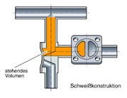
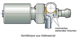
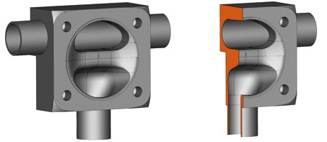
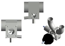
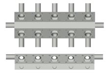
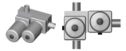
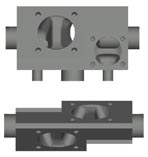
The below illustrations compare the hold up volume and the compact
design of a multiport block valve to a welded valve configuration:
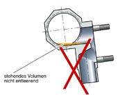
The complete drainability is an important consideration for the design of multiport valves. The following illustration shows the correct and incorrect installation of a standard T-valve:
Multiport block valves with main line open
for example T-Valve or ZDL-Valve
Description
P&ID
Illustration (actuators and other options are included in some of the illustrations)
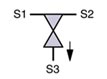
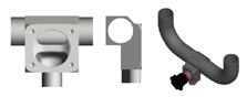
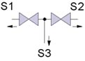
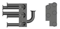
1.1) T-Valve or ZDL Valve 1x Point of use valve port
Recommended Installation: S3 down Illustration right side: T-Valve with U-bend added fordistribution loop installation
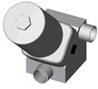
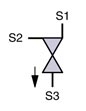
1.15) MA 31 1x Point of use valve port
Recommended Installation: S3 horizontal
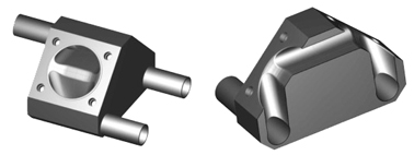
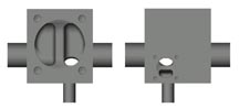
1.2) ML 3/1 1x Point of use valve port withintegrated directional flow 90°to the main line
Recommended Installation: S3 down
1.3) MY 3/1 1x Point of use valve port withY main line inlet and outlet. Thusthe inlet and outlet dimensionof the main line is reduced and can meet the centreline dimensions of an ASME BPE 180° U-bend.
Recommended Installation: S3 down
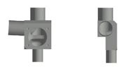
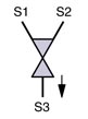
1.4) MZ 4/2 1x Point of use valve port 1x Integral loop sample valve port can be opposite positioned as showed on the picture or sidewise.
Recommended Installation: S3 down
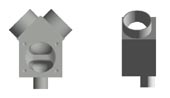
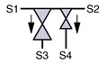
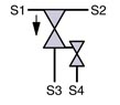
1.45) MT 4/2 1x Point of use valve port 1x Integral loop sample valve port Two parallel one-sided orientatedvalve actuators.
Recommended Installation: S3 down
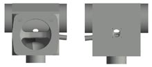
1.55) MFE 4/2 2x Point of use Valve ports The number of valve ports is variable
Recommended Installation: S2 vertical down
1.6) MX 4/2 1x Point of use valve port 1x Integral sample purge valve valve port below the weir can beopposite positioned as showed onthe picture or sidewise.
Recommended Installation: S3 vertical down
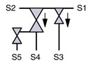
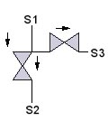
1.7) MW 5/3 2x Point of use valve port 1x Integral loop sample valve port 1x Integral sample purge valve portbelow the weir.
Recommended Installation: S4 down
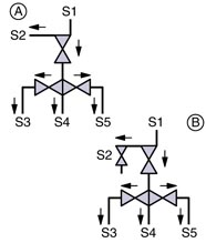
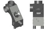
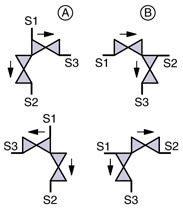
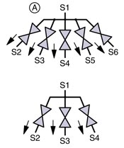
1.8) MF 6/4 1x Point of use valve port with integrateddirectional flow 90° to the main line 1.8 A) 2x Integral sample purge valve port below the weir 1.8 B) 1x Integral loop sample purge valve port 2x Integral sample purge valve port below the weir
Recommended Installation: S5 and S3 down, S4 horizontal
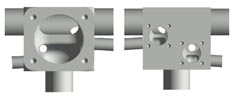
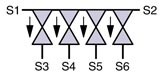
1.9) MT 6/4 4x Point of use valve ports The number of valve ports is variable
Recommended Installation: S1 and S2 horizontal S3...S6 vertical down or vertical up orientation. S1 and S2 can be vertical if tube outlets S3 to S6 are positioned to the lowest point of valve pocket
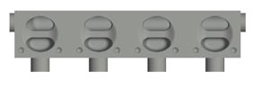
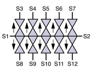
1.10) MX 12/10 10x Point of use valve ports The number of valve ports is variable
Recommended Installation: S1 and S2 horizontal S3 to S10 horizontal or vertical uporientation. S1 and S2 can be vertical if tube outlets S3 to S10 are positioned to the lowest point of valve pocket
Multiport block valves with all lines and valve
ports able to close
Description
P&ID
Illustration (actuators and other options are included in some of the illustrations)
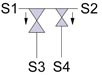
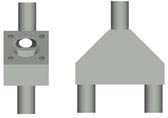
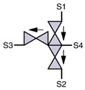
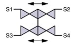
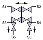
2.8) MF 4/4 4x Valves vertical Chromotography valve without bypass MF 4/5 (A) 5x Valves vertical Chromatography valve with bypass
Recommended Installation: S2 and S4 horizontal S1 and S3 vertical
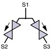
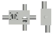
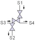
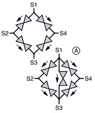
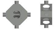
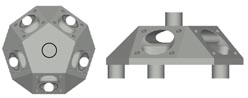
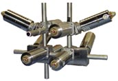
2.9) MC 4/3 Star Design 3x Valves vertical MC 6/5 Star Design 5x Valves vertical
Recommended Installation: S1 vertical Depending on the diameter the star design is available with up to 7 valves. The star design has also been manufactured with the opposing multiport block valves with one common part connection.
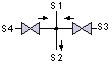
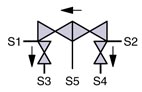
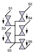
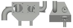
2.11) MF 6/6 4x Valves horizontal 2x Valves vertical S5 and S6 for drainage
Recommended Installation: S5 and S6 down
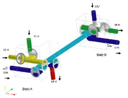
2.12) Example: Multiport valve assembly designed based on a P&ID combination of multiport block and welded vale configurations with full drain ability and minimal 4:1 dead leg. Designed and manufactured by SED